
Gamepads
Description
The SNESpad core manages one or more gamepads of the Super Nintendo Entertainment System in parallel. The button information is provided statically at a simple interface with dedicated signal lines. The core has to be configured to fit into the integrating system. Details about this are given in the section "Integration" below.
I have mainly used this core to connect a SNES gamepad to the arcade games at FPGA Arcade.
Adapter Hardware
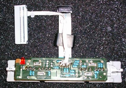
The required hardware setup is pretty simple if you reuse the connector of a SNES console. It is quite robust and offers all connections centrally on the bottom side of the PCB at the pins for the cable socket. In addition, you will need an external 5V power source. Such a configuration is shown in the following picture.
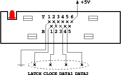
Pin B1 is the common Data Latch signal for Pad 1 and Pad 2. The pins B2 and T2 are the Data Clock for Pad 1 and Pad 2, respectively. They have to be connected together to pad_clock_i as the core clocks both pads simultaneously. Pin B3 is the Serial Data of Pad 1 and Pin B4 is the Serial Data of Pad 2. Each data line requires a 10 kOhm pull-up resistor.
Integration
The interface of the SNESpad core is straight forward. It requires:
- a clock signal which is evaluated on the rising edge by the internal registers
- an asynchronous reset (active level is configurable)
- connections to the gamepad(s)
The button outputs should be self-describing.
Configuration of the core is done via generics in the instantiation. There are four generic parameters:
- num_pads_g - Number of pads connected to this controller instance (1 to n)
- reset_level_g - Active level of the asynchronous reset at port reset_i (0 = low active, 1 = high active)
- button_level_g - Active level of the button outputs (0 = low active, 1 = high active)
- clocks_per_6us_g - Number of clk_i cycles that elapse during 6 us (2 to x)
Button outputs and pad data input are arrays of num_pads_g width. The assignment is 1:1. i.e. the pad connected to pad_data_i(i) will propagate its button status to but_a_o(i), but_b_o(i) etc. where i ranges from 0 to n-1.
The communication with the SNES gamepad relies on a timebase of approximately 6 μs. It is therefore necessary to adjust the counters inside the core via the clock_per_6us_g generic parameter. Let's assume an example where the system clock is running at 20 MHz. There are 20 clock cycles during 1 μs, so the generic has to be set to 6 x 20 = 120.